


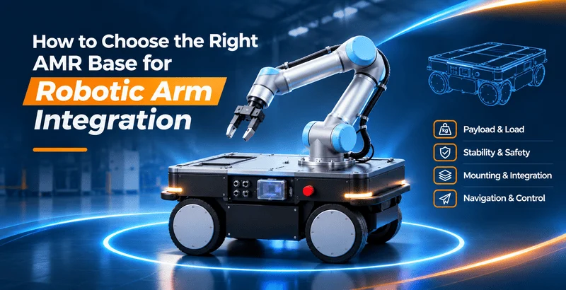
自律移動ロボット(AMR)にロボットアームを搭載することで、作業エリア間を移動し、資材運搬、ピッキング、機械への荷積み・荷下ろしなどの作業を行うことが可能になります。この種のシステムは「移動型マニピュレーター」として知られています。安全で安定した、信頼性の高い運用を実現するには、適切なAMRシャーシの選定が不可欠です。.
では、ロボットアームを組み込むためのAMR移動ロボットシャーシは、どのように選べばよいのでしょうか?最大積載量は、その判断基準の一つに過ぎません。アームの重量や可動範囲、全体的な安定性、取り付け設計、ナビゲーション性能、システムの互換性なども考慮する必要があります。このガイドでは、適切なプラットフォームを選定するための7つの実践的な手順を解説します。.
ステップ 1:ロボットアームの統合要件を定義する
AMRシャーシの仕様を比較する前に、ロボットアームとその用途を明確に定義しておく必要があります。アームによって、重量、リーチ、可搬重量、および取り付け要件は異なります。また、同じアームであっても、軽作業のピッキングに使用する場合と、重量のあるワークピースの取り扱いを行う場合とでは、移動ベースに求められる要件が大きく異なる場合があります。.
1.1 ロボットアームの主要仕様の確認
まずはロボットアームメーカーのデータシートを確認してください。特に以下の仕様に注意を払ってください:
| 仕様 | その意味 | シャーシ選定においてなぜ重要なのか |
|---|---|---|
| アームの重量 | ロボットアーム自体の重量。通常、エンドエフェクタの重量は含まれない。. | AMRシャーシが支える荷重の大部分を占めています。. |
| 定格ペイロード | アームの先端で許容される最大荷重。. | ワークピースの許容重量を決定するのに役立ちます。これはアーム自体の重量ではありません。. |
| 最大リーチ | 腕が伸びる最長距離。. | リーチが長くなると、重心のずれが大きくなり、転倒のリスクが高まる可能性があります。. |
| 取り付け方法とベースの寸法 | アームの取り付け面積、ボルトパターン、および固定方法。. | 上部プラットフォームと取り付け構造が互換性があるかどうかを判定します。. |
| エンドエフェクタとワークピースの重量 | グリッパー、吸引ツール、その他の工具、および把持対象物の重量。. | 総荷重および安定性の計算には、これを必ず含める必要があります。. |
重要:定格可搬重量が5 kgのロボットアームであっても、その重量が必ずしも5 kgであるとは限りません。移動式ベースにかかる荷重を過小評価しないよう、アームの重量、ツールの重量、およびワークピースの重量をそれぞれ個別に確認してください。.
1.2 タスクと運用環境の定義
作業現場は、ロボットアームの仕様と同じくらい重要です。以下の質問をしてみてください:
- 用途:このアームは、倉庫でのピッキング、機械のチーフ作業、資材運搬、検査、サンプリング、あるいは自動試験のいずれを行う予定ですか?
- 稼働環境:ロボットは屋内、屋外、あるいはその両方で稼働する予定ですか?
- 床の状態:傾斜、敷居、床の隙間、金属製の格子、または滑りやすい箇所はありますか?
- 利用可能なスペース:通路の幅はどれくらいですか? 旋回スペースはどれくらいありますか? 人とロボットは同じエリアを共有することになりますか?
- デューティサイクル:システムは1日あたり何時間稼働しますか?1時間あたり、何回の搬送およびピッキングサイクルが必要ですか?
これらの詳細は、シャーシの寸法、駆動システム、車輪の選定、ナビゲーションセンサー、バッテリー容量、および安全対策に影響を与えます。現場に傾斜や障害物がある場合は、単に「床が平らではない」と説明するのではなく、写真や測定値を提示してください。.
1.3 AMRが移動中にアームを動作させるかどうかを決定する
一般的なワークフローの一つは、アームを収納した状態で移動し、作業を行うために停止するというものです。AMRは作業ステーションまで移動し、安全に停止した後、アームが作業を行います。作業が完了すると、アームは搬送位置に戻り、その後AMRが再び移動を開始します。.
AMRが移動している間もアームを伸ばしたままにしたり、作業を継続したりする必要がある場合、設計の難易度は高まります。動的安定性、協調動作、衝突リスク、および安全制御について、追加の検証が必要となります。初めての移動型マニピュレータプロジェクトでは、「停止して作業する」というアプローチの方が、統合や検証が容易な場合が多いです。.
ステップ 2:AMRシャーシの積載量を算出し、安定性を評価する
用途を定義したら、AMRシャーシが支える必要がある重量を算出します。よくある間違いとして、アームが保持するワークのみを計算対象としてしまうことが挙げられます。実際には、シャーシが支えるすべての構成部品を含める必要があります。.
2.1 搭載機器の総重量を算出する
簡単な最初の推定値は次のとおりです:
総搭載荷重=ロボットアーム+取り付けブラケットまたはプレート+エンドエフェクタ+最大加工物+オンボードコントローラ、センサー、コンピュータ、およびその他の付属品。.
たとえば、モバイルマニピュレーターのプロジェクトでは、次のような構成になる場合があります:
| コンポーネント | 例:重さ |
|---|---|
| ロボットアーム | 18 kg |
| 取り付けブラケットおよびアダプタープレート | 8 kg |
| グリッパー(エンドエフェクタ) | 3 kg |
| 最大加工物 | 5 kg |
| 車載コンピュータとセンサー | 4 kg |
| 総積載量 | 38 kg |
この例では、シャーシは搭載機器と積載物の合計重量が少なくとも38 kgに耐えられる必要があります。しかし、最大積載量38 kgと謳われているシャーシが、必ずしも適切な選択肢であるとは限りません。.
また、荷重の重心、移動速度、床の状態、傾斜、および動荷重についても確認する必要があります。実際の使用状況に基づいて、適切な設計余裕を設けてください。.
積載量の定義はメーカーによって異なる場合もあります。シャーシの一部として供給されるバッテリー、モーター、車体は、通常、シャーシ自体の重量に含まれます。これらに加えて、上部に取り付けられた追加のバッテリー、キャビネット、またはモジュールは、搭載荷重として計算する必要があります。定格積載量、最大積載量、および車両総重量の意味について、サプライヤーに確認してください。.
2.2 重心と荷重分布の確認
モバイルマニピュレーターが安定した状態を保てるかどうかは、重量だけで決まるわけではありません。その重量の位置も重要な要素となります。.
アームがシャーシよりかなり高い位置に取り付けられている場合、中心からずれている場合、あるいは片側に大きく張り出している場合、システムの重心がずれる可能性があります。これにより、アームの動作中、制動時、旋回時、あるいは凹凸のある地面を走行する際に、転倒のリスクが高まる恐れがあります。.
片方の端に重りがついた長い棒を持っていると想像してみてください。重りが体から離れるほど、バランスを保つのが難しくなります。ロボットアームも、外側に伸ばすとき、同様の現象が起こります。.
取り付け位置、アームの動作姿勢、および許容される重心の範囲には特に注意を払ってください。.
アームは、シャーシメーカーが承認した積載範囲内に取り付けてください。不必要な高さに取り付けることや、中心からずれた位置への設置は避けてください。最も重いワークピースを使用して、フルリーチ、サイドリーチ、およびその他の過酷なアームの位置について評価を行ってください。.
計画している速度および床の状態において、許容荷重中心、重心高さ、およびオフセットの制限値については、サプライヤーに確認してください。.
荷重が高すぎたり、中心からずれていたりすると、ロボットの移動時の安定性が低下することもあります。ロボットアームの統合においては、積載量だけでなく、重心や荷重の分布も同様に重要です。.
2.3 運動中の動的安定性の評価
静止時には安定しているシステムでも、アームが加速したり、回転したり、伸展したり、あるいは急停止したりすると、その挙動が異なる場合があります。また、シャーシも、発進、制動、旋回時に、変化する力を受けます。.
安定性評価では、最も過酷な運転条件を対象とすべきである:
最も重いワークピースを保持しているアームについて、不適切なリーチ、高速回転や伸展、急停止、および運動方向の変化といった状況を考慮に入れること。また、加速、制動、旋回時の全負荷状態のシャーシに加え、許容傾斜、床の継ぎ目、および凹凸のある路面を走行する場合についても評価を行うこと。.
安定性試験の代わりとして、単純な積載率を使用しないでください。サプライヤーと協力して構成全体を評価し、管理された試験条件下で検証を行ってください。.
ステップ3:ロボットアームの取り付け互換性を確認する
積載量と安定性が問題ないように確認できたら、アームを確実に取り付けることができるか確認してください。すべてのAMRシャーシに適切な上部プラットフォームがあるわけではありません。ボルト穴の位置が合っていたとしても、構造に必要な強度、剛性、またはスペースが不足している可能性があります。.
3.1 プラットフォームの寸法および取り付けインターフェースの確認
ご購入前に、以下の機械的な詳細をご確認ください:
- 上部プラットフォームの長さ、幅、有効取り付け面積、および床面からの高さ。.
- 取り付け穴の数、サイズ、間隔、ねじの種類、および設置可能な位置。.
- アームとシャーシの間に、アダプタープレート、補強プレート、あるいは特注のブラケットが必要かどうか。.
- Whether the arm can move through its operating range without hitting the vehicle body, wheels, sensors, or nearby equipment.
Before purchasing, request the chassis outline drawing, top mounting drawing, and available CAD or 3D files. Compare them with the robotic arm’s installation drawings. Product photos and overall dimensions alone are rarely enough.
3.2 構造強度、剛性、および振動の確認
A robotic arm applies forces and moments to its mounting platform during operation. If the top plate, bracket, or fasteners are not stiff enough, the arm may shake, vibrate, or lose positioning accuracy. Long-term reliability may also suffer.
The chassis supplier needs the arm’s weight, reach, payload, and operating cycle to assess the mounting structure. If a custom bracket is required, review its material, plate thickness, fastening method, and maintenance access. The goal is not just to make the arm fit. The mounting assembly must withstand both static and dynamic loads.
3.3 センサーの視認性、ケーブル、およびメンテナンス用アクセス経路の確認
After installation, the robotic arm may block LiDAR, cameras, ultrasonic sensors, or emergency-stop access. Moving joints may also pull, pinch, or twist cables and air hoses.
Check the full range of arm movement for blocked navigation or obstacle-detection sensors. Route power cables, communication lines, and air hoses with enough slack, secure fixing points, and suitable protection.
Keep the battery, controllers, protective devices, and emergency-stop buttons accessible. Check for pinch points, interference, collision risks, and possible contact with people.
ステップ4:AMRドライブとナビゲーションを現場の状況に合わせて調整する
An AMR carrying a robotic arm must do more than move. It needs to travel reliably through the worksite and stop in a position where the arm can perform its task. Drive layout, robot size, obstacle clearance, and positioning performance should match the actual site.
4.1 駆動システムを作業現場に合わせて選定する
Different mobile robot chassis designs have different strengths. More wheels or a more complex drive system do not automatically mean better performance.
| 駆動構成 | Typical Characteristics | What to Check |
|---|---|---|
| 2WD differential drive | Relatively simple design. Common on smooth indoor floors. Turns by varying left and right wheel speeds. | Aisle width, floor quality, turning space, and payload. |
| 4WD (four-wheel drive) | Drives multiple wheels and can provide greater traction in suitable configurations. | Surface grip, slopes, tires, and steering method. |
| 4WD-4WS (four-wheel drive, four-wheel steering) | Combines four driven wheels with four-wheel steering. Available steering modes depend on the specific design. | Maneuverability, turning path, control behavior, and mechanical complexity. |
| Omnidirectional chassis | Some designs allow sideways or diagonal travel for easier alignment with workstations. | Whether lateral movement is needed, plus floor quality, load, and positioning needs. |
For a robot following fixed aisles on a smooth warehouse floor, a simple differential-drive chassis may be enough. If the site needs greater steering flexibility or traction, consider a 4WD-4WS platform. Prioritize omnidirectional movement only when sideways positioning is useful. Make the final decision using full-load tests on the intended route.
4.2 ナビゲーション精度の確認とワークステーションのドッキング
Navigation helps the AMR reach the correct workstation. Docking performance determines how consistently it stops in the required position and orientation.
Chassis positioning accuracy is not the same as robotic arm tool accuracy. Docking errors, vehicle orientation, uneven floors, mounting deflection, arm accuracy, and changes in object position can all affect the end effector’s final location.
For larger objects with generous position tolerance, standard navigation and a suitable workstation layout may be enough. Precision loading, insertion, or small-part picking may require accurate docking, machine vision, locating fixtures, or an extra calibration step.
Ask the supplier how localization accuracy and repeat docking accuracy were measured. A single accuracy number without test conditions is not enough.
4.3 勾配、閾値、およびクリアランスの確認
Measure the narrowest aisles and doorways, turning areas, slope angles, thresholds, and floor joints. Use the full assembled robot dimensions, including the arm, mounting structure, and workpiece.
A bare chassis that can climb a slope may not be suitable for the same slope after a robotic arm is installed. A higher or offset center of gravity can change the allowable speed, slope, and braking conditions. Ask for an assessment of the integrated system, not just a demonstration of the unloaded chassis.
ステップ 5:電源、ソフトウェア、および安全システムの統合を確認する
A chassis and robotic arm may both work well on their own but still require substantial integration work. Check electrical compatibility, communication, coordinated control, and safe fault handling.
5.1 バッテリー容量とロボットアームの電力要件を整合させる
Review the arm’s and onboard equipment’s specifications for operating voltage, continuous power, peak power, startup current, and duty cycle. Compare these requirements with the AMR’s available power outputs and battery capacity.
Confirm that the chassis provides the required output voltage and enough continuous and peak current. Check whether the arm needs a separate power supply, a DC-DC converter, or electrical isolation.
Estimate battery runtime across the real duty cycle: travel, waiting, arm movement, gripper use, and sensors. If you add a battery or power module, include its weight in the mounted load and check its mounting position and cooling requirements.
Do not estimate runtime from amp-hours (Ah) alone. Voltage, power draw, duty cycle, usable battery capacity, and temperature all affect operating time. Ask for an estimate based on your task cycle and confirm it through integrated system testing.
5.2 ROS 2、API、および通信の互換性を確認する
If your project uses ROS 2 (Robot Operating System 2), confirm that the AMR chassis and robotic arm have compatible drivers, documentation, and communication methods. Depending on the product, options may include ROS 2 packages, SDKs, APIs, Ethernet, or CAN.
However, ROS 2 support does not mean plug-and-play integration. The integration team must also check the ROS 2 distribution, driver versions, topics, services, actions, coordinate frames, time synchronization, motion commands, and fault feedback.
The chassis and arm must use a consistent coordinate system. The navigation system also needs an accurate representation of the space occupied by the arm and mounted equipment.
Before purchase, request interface specifications, SDK/API documentation, ROS 2 driver details, communication protocols, sample code, and information about technical support for secondary development.
5.3 安全機能の計画と協調制御
Adding a robotic arm changes the robot’s operating envelope. The arm may extend beyond the chassis, enter pedestrian areas, or block safety sensors. Assess the chassis, arm, tool, surrounding equipment, and people as one system.
Confirm how an emergency stop affects both the AMR and the arm, and what safe state each system enters. Define the conditions for travel, arm operation, and maintenance modes.
Decide whether the arm must return to its transport position before the chassis can move, and whether chassis movement is blocked while the arm is working. Make sure safety scanners and obstacle-detection sensors still provide suitable coverage after integration.
For driverless industrial trucks and their systems, ISO 3691-4:2023 provides relevant safety requirements and verification guidance. Whether it applies to your project depends on the equipment, local regulations, and risk assessment. An AMR chassis with emergency-stop and obstacle-avoidance functions does not automatically make the complete mobile manipulator safe.
ステップ6:標準型とカスタム型のAMRシャーシ:どちらを選ぶべきか?
By this point, you should have a clear set of requirements. Use it to decide whether a standard mobile robot platform will work or whether customization is necessary. Neither option is always better. The right choice depends on the project’s real constraints.
6.1 どのような場合に、標準的なAMRシャーシの方が適しているのか?
A standard chassis is often the simpler option when its payload rating, center-of-gravity limits, dimensions, mounting interface, drive system, navigation, power, and software interfaces meet your needs. It may reduce design effort and simplify maintenance, spare parts, and repeat production.
Still, the published specifications must apply to the actual mounted equipment. A 100 kg maximum payload rating does not, by itself, confirm compatibility with a particular robotic arm. Check the load position, working posture, travel speed, and test conditions. You can compare examples in Fdata’s mobile robot chassis lineup.
6.2 どのような場合にカスタムAMRシャーシが必要になるのか?
Consider a custom AMR chassis when standard models cannot meet essential project requirements.
Customization may be needed for unusual arm mounting dimensions or bolt patterns, a reinforced top plate, or an adapter bracket. It may also be necessary when the total load, center of gravity, or load distribution exceeds the limits of a standard chassis.
Other reasons include narrow aisles, low equipment clearance, special turning or floor conditions, and project-specific power, sensor, communication, or software interfaces. OEM/ODM projects may also require a dedicated enclosure, dimensions, branding, or production configuration.
Customization also adds design, validation, lead time, and maintenance costs. First identify the gaps in the standard product. Then ask the supplier to define the required changes, cost, schedule, testing, and spare-parts plan.
6.3 見積もりを依頼する際、サプライヤーには何を提出すべきか?
A useful quotation starts with accurate application data. Prepare the following:
- Robotic arm brand and model, arm weight, rated payload, and maximum reach.
- End effector weight, maximum workpiece weight, and most demanding arm positions.
- Arm mounting drawings, bolt pattern, planned mounting height, and mounting location.
- Weights of other onboard equipment, such as controllers, computers, sensors, and extra batteries.
- Site photos or layout drawings, aisle widths, slopes, thresholds, and floor type.
- Operating sequence, including whether the arm retracts during travel and whether precise docking is required.
- Software and interface needs, such as ROS 2 version, SDK/API, Ethernet, CAN, and emergency-stop connections.
If some information is not yet available, start with the arm model and application. Ask the supplier what else is needed. Do not leave out the maximum workpiece weight or extended arm positions just to get a faster quote.
ステップ7:購入前にAMRシャーシをテストする
Datasheets and CAD drawings help narrow down your choices, but they cannot replace testing. Where possible, validate the actual arm, mounting structure, and loads under conditions close to the real application.
7.1 仕様書および機械図面の確認
Review how the supplier defines rated and maximum payload, the related test conditions, and the permitted load center. Compare arm and chassis mounting drawings for installation space, bolt holes, and cable routing.
Also check supply voltage, continuous and peak current, software drivers, communication protocols, and safety interfaces. Compare the assembled robot’s dimensions with actual aisles, slopes, thresholds, workstations, and maintenance space.
7.2 取り付け強度、積載量、および安定性の試験
With the arm installed, test the retracted position, full reach, side reach, and maximum workpiece load in a controlled environment after completing a suitable risk assessment. Watch for unusual vibration, structural deflection, wheel unloading, tilting, or other signs of instability.
Also check the fully loaded chassis during starting, braking, turning, and travel along approved routes. The project team and supplier should agree on test speeds, slopes, and loads. Do not attempt uncontrolled limit tests.
7.3 ナビゲーション、ドッキング、およびアームの協調動作の試験
Run the robot along the planned route several times. Record its stopping position, orientation, and repeat docking performance. Then have the arm complete typical tasks at those stopping positions to see whether vision guidance, fixtures, or additional calibration are required.
Test the full control sequence as well: when the chassis can move, when the arm can extend, and how both systems respond to communication loss or emergency stops. Testing each machine separately is not enough.
7.4 バッテリー駆動時間および連続動作の試験
Run a representative full work cycle and record power consumption and temperature during travel, waiting, picking, standby, and charging. Runtime depends on load, speed, route, arm activity, ambient temperature, and battery condition. Use the complete system’s measured performance as the final reference.
購入の受入基準を定義する
Define the test items, loads, routes, docking requirements, continuous operating time, fault responses, and pass/fail criteria in the project plan or purchase agreement. Depending on the project, arrange a factory acceptance test (FAT) and a site acceptance test (SAT). A single demonstration should not be the only basis for acceptance.
Fdata AMR シャーシのオプション:標準プラットフォームとカスタム統合
If you are looking for an AMR chassis for robotic arm integration, start by comparing standard platforms against your payload, mounting dimensions, operating environment, and interface requirements. Then decide whether a customized configuration is necessary.
Fdata supplies mobile robot chassis and OEM/ODM solutions. Its A012 series uses a four-wheel-drive, four-wheel-steering (4WD-4WS) configuration and can serve as a starting point for mobile manipulation, inspection, and other robot integration projects.
Here is a quick comparison of the A012 and A012 Plus:
| プラットフォーム | Key Specifications | Potential Fit |
|---|---|---|
| Fdata A012 mobile robot platform | 4WD-4WS; approx. 620 × 520 × 340 mm; 44 kg chassis weight; 60 kg maximum payload; 8 km/h maximum speed; ROS1/ROS2 listed. | A compact starting point for lighter mounted equipment, subject to checks on total load, center of gravity, mounting, and working conditions. |
| Fdata A012 Plus platform | 4WD-4WS; approx. 920 × 700 × 420 mm; 80 kg chassis weight; 100 kg maximum payload; 8 km/h maximum speed; ROS1/ROS2 listed. | A starting point for projects that need a higher payload class. Mounting interfaces, load structures, and sensor configurations can be assessed for customization. |
Specification note: These figures are based on Fdata’s published model specification tables and are intended for initial comparison only. A maximum payload rating is not a guarantee for every mounting position, center-of-gravity height, speed, or terrain condition. Request the latest datasheet for the exact configuration and have the completed system reviewed.
Beyond standard platforms, Fdata offers custom mobile robot and OEM/ODM solutions. Depending on project requirements, this can include changes to load structures, mounting interfaces, sensor layouts, and software integration. Fdata also describes API support for secondary development on the A012 Plus product page.
AMRシャーシの選定に関するアドバイスについては、Fdataまでお問い合わせください
To help the Fdata team evaluate your project, provide the key information below.
Share the arm brand and model, its weight, reach, and rated payload. Include the gripper and heaviest workpiece, plus typical working positions and any mounting drawings or CAD files.
Also provide the required chassis size, site and floor conditions, slope and aisle details, power needs, ROS 2 or other communication requirements, and safety interfaces.
Not sure which AMR chassis is right for your robotic arm project?
Contact the Fdata technical team for advice on chassis selection and custom integration.
まとめ
Choosing an AMR chassis for robotic arm integration takes more than checking maximum payload. Review the arm specifications, application requirements, stability, mounting design, navigation, and system compatibility. Then validate the proposed setup through practical testing.
The best AMR chassis is not simply the one with the highest specification on paper. It is the one that allows the arm, chassis, mounted equipment, and control system to work reliably in the intended environment. Clear project requirements and early discussions with suppliers can reduce selection mistakes, rework, and integration costs.
よくある質問
ロボットアームを搭載する場合、AMRシャーシにはどの程度の積載能力が必要ですか?
AMRシャーシに必要な積載容量は、ロボットアーム、取り付けブラケット、エンドエフェクタ、最大加工物、および搭載機器の総重量によって決まります。また、シャーシは予想される荷重分布や動的荷重にも耐えられなければなりません。積載容量を決定する際は、必ず許容重心位置および動作条件を確認してください。.
標準的なAMRシャーシをロボットアームの組み込みに使用することは可能ですか?
Yes, a standard AMR chassis can support robotic arm integration if its load capacity, mounting structure, power supply, and control interfaces meet the arm’s requirements. Some applications may need additional mounting brackets or reinforced platforms. If standard configurations are insufficient, a customized AMR chassis may be necessary.
産業用ロボットアームと協働ロボットは、同じAMRシャーシを使用できますか?
はい、産業用ロボットアームと協働ロボット(コボット)は、それぞれの要件が満たされていれば、同じAMRシャーシモデルを使用することができます。互換性は、アームの重量、可動範囲、取り付け寸法、電力要件、および動作力によって異なります。組み合わせごとに、個別の安定性および安全性の評価が必要となります。.
ロボットアームの可動範囲が長くなると、AMRのシャーシもより大型のものが必要になるのでしょうか?
Not necessarily. A longer robotic arm reach can increase the tipping moment, but it does not automatically require a larger AMR chassis. The required chassis size depends on the arm’s weight, mounting height, center of gravity, load distribution, and platform geometry. A stability assessment is essential before making the final selection.
AMRに搭載されたロボットアームには、追加のスタビライザーが必要ですか?
AMRに搭載されたロボットアームのすべてに、追加の安定化装置が必要なわけではありません。適切に設計された移動ベースであれば、静止状態での動作中に十分な安定性を確保できる場合があります。ただし、重い積載物、アームの伸長位置、あるいは精密な作業を行う場合には、安定性と位置決め性能を向上させるために、安定化用脚、機械式ロック、その他の支持システムが必要になる場合があります。.
1台のAMRシャーシで、異なるメーカー製のロボットアームに対応することは可能ですか?
はい、モジュラー式のAMRシャーシであれば、各メーカーのロボットアームの機械的、電気的、およびソフトウェア上の要件が互換性さえあれば、それらに対応できる可能性があります。主な考慮事項としては、取り付け寸法、可搬重量の制限、電源、通信インターフェースなどが挙げられます。将来のアップグレードを見据えて、柔軟な取り付けオプションと、開発用インターフェースへのアクセスが容易なシャーシを選択することをお勧めします。.
