


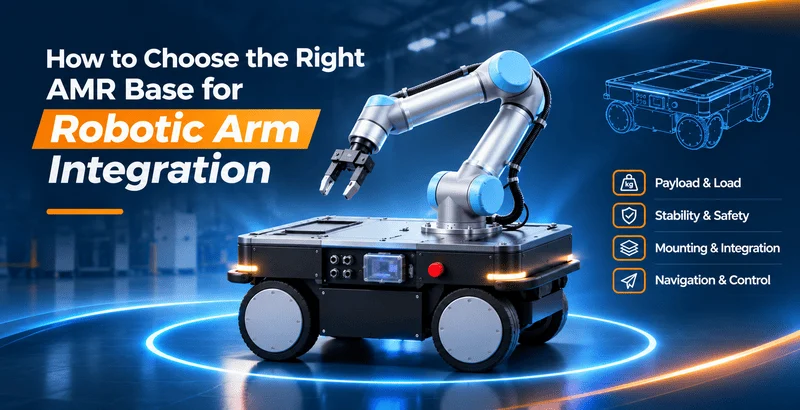
자율 주행 로봇(AMR)에 로봇 팔을 장착하면 작업 구역 간을 이동하며 자재 취급, 피킹, 기계 적재 및 하역과 같은 작업을 수행할 수 있습니다. 이러한 유형의 시스템을 ‘이동형 매니퓰레이터’라고 합니다. 안전하고 안정적이며 신뢰할 수 있는 작동을 위해서는 적합한 AMR 섀시를 선택하는 것이 필수적입니다.
그렇다면 로봇 팔을 통합하기 위해 AMR 이동형 로봇 섀시를 어떻게 선택해야 할까요? 최대 적재량은 여러 고려 사항 중 하나일 뿐입니다. 로봇 팔의 무게와 작업 반경, 전반적인 안정성, 장착 설계, 주행 성능, 시스템 호환성 등도 함께 고려해야 합니다. 이 가이드는 적합한 플랫폼을 선택하는 데 도움이 되는 7가지 실용적인 단계를 안내합니다.
1단계: 로봇 팔 통합 요구 사항 정의하기
AMR 섀시 사양을 비교하기 전에, 로봇 팔과 그 용도를 먼저 명확히 정의해야 합니다. 로봇 팔마다 무게, 작업 반경, 적재 하중, 장착 요건이 서로 다릅니다. 심지어 동일한 로봇 팔이라도 가벼운 피킹 작업에 사용할 때와 무거운 공작물 취급에 사용할 때, 이동식 베이스에 요구되는 조건이 크게 달라질 수 있습니다.
1.1 로봇 팔의 주요 사양 확인
먼저 로봇 팔 제조사의 데이터시트부터 확인하십시오. 특히 다음 사양에 주의를 기울이십시오:
| 사양 | 그 의미는 무엇인가 | 섀시 선정에 있어 그 중요성 |
|---|---|---|
| 팔의 무게 | 로봇 팔 자체의 무게로, 일반적으로 엔드 이펙터는 제외됩니다. | AMR 섀시가 지탱해야 하는 하중의 상당 부분을 차지합니다. |
| 정격 적재 하중 | 암 끝부분에서 허용되는 최대 하중. | 허용되는 공작물 중량을 결정하는 데 도움이 됩니다. 이는 암 자체의 중량이 아닙니다. |
| 최대 도달 거리 | 팔이 뻗을 수 있는 가장 먼 거리. | 리치(reach)가 길어지면 무게 중심이 더 크게 이동하여 전복 위험이 커질 수 있습니다. |
| 장착 방법 및 베이스 치수 | 암의 장착 면적, 볼트 배열 및 고정 방식. | 상단 플랫폼과 장착 구조가 호환되는지 여부를 확인합니다. |
| 엔드 이펙터 및 공작물 중량 | 그리퍼, 흡착 공구, 기타 공구 및 취급 대상물의 무게. | 총 하중 및 안정성 계산에 반드시 포함되어야 합니다. |
중요: 정격 적재량이 5kg인 로봇 팔의 무게가 반드시 5kg인 것은 아닙니다. 이동식 베이스에 가해지는 하중을 과소평가하지 않도록 팔의 무게, 공구의 무게, 가공물의 무게를 각각 따로 확인하십시오.
1.2 과제 및 운영 환경 정의
작업 현장은 로봇 팔의 사양만큼이나 중요합니다. 다음 질문들을 확인해 보십시오:
- 적용 분야: 해당 암은 창고 피킹, 기계 보조, 자재 취급, 검사, 샘플링 또는 자동화된 테스트 작업을 수행할 예정입니까?
- 운영 환경: 로봇은 실내, 실외, 아니면 두 환경 모두에서 작동할 예정인가요?
- 바닥 상태: 경사, 문턱, 바닥 틈, 금속 격자, 미끄러운 곳이 있습니까?
- 가용 공간: 통로 폭은 얼마나 되나요? 회전할 수 있는 공간은 얼마나 되나요? 사람과 로봇이 같은 공간을 공유하게 될까요?
- 작동 주기: 시스템은 매일 몇 시간 동안 가동되나요? 시간당 몇 번의 이송 및 피킹 주기가 필요한가요?
이러한 세부 사항은 차체 치수, 구동 시스템, 휠 선택, 주행 센서, 배터리 용량 및 안전 조치에 영향을 미칩니다. 현장에 경사면이나 장애물이 있는 경우, 단순히 바닥이 고르지 않다고 설명하는 대신 사진과 측정값을 제공해 주십시오.
1.3 AMR이 이동 중일 때 암이 작동할지 여부를 결정한다
흔히 사용되는 작업 흐름 중 하나는 팔을 접은 상태로 이동한 다음, 작업을 위해 정지하는 방식입니다. AMR은 작업대로 이동하여 안전하게 정지한 후, 팔이 작업을 수행하도록 합니다. 작업이 완료되면 팔은 이동 위치로 돌아간 뒤, AMR이 다시 이동합니다.
AMR이 이동하는 동안 팔을 뻗은 상태로 유지하거나 작업을 계속해야 하는 경우, 설계에 더 많은 고려가 필요합니다. 동적 안정성, 동작 연동, 충돌 위험 및 안전 제어에 대한 추가적인 검증이 필요해집니다. 첫 번째 이동형 매니퓰레이터 프로젝트의 경우, ‘정지 후 작업(stop-and-work)’ 방식을 채택하는 것이 통합 및 검증 측면에서 더 쉬운 경우가 많습니다.
2단계: AMR 섀시 탑재량 계산 및 안정성 평가
용도를 정의한 후, AMR 섀시가 지탱해야 할 하중을 계산하십시오. 흔히 저지르는 실수는 암이 잡고 있는 공작물만 계산하는 것입니다. 실제로는 섀시가 지지하는 모든 구성 요소를 포함해야 합니다.
2.1 장착된 장비의 총 중량 계산
간단한 초기 추정치는 다음과 같습니다:
총 장착 하중 = 로봇 팔 + 장착 브래킷 또는 플레이트 + 엔드 이펙터 + 최대 공작물 + 온보드 컨트롤러, 센서, 컴퓨터 및 기타 부속품.
예를 들어, 모바일 매니퓰레이터 프로젝트는 다음과 같은 구성을 가질 수 있습니다:
| 구성 요소 | 예시 가중치 |
|---|---|
| 로봇 팔 | 18kg |
| 장착 브라켓 및 어댑터 플레이트 | 8kg |
| 그리퍼 (엔드 이펙터) | 3kg |
| 최대 공작물 | 5kg |
| 차량용 컴퓨터 및 센서 | 4kg |
| 총 적재 하중 | 38kg |
이 예에서 섀시는 장착된 장비와 적재물의 무게를 합쳐 최소 38kg을 지탱할 수 있어야 합니다. 하지만 최대 적재량이 38kg이라고 광고되는 섀시가 무조건 적합한 선택이라고 볼 수는 없습니다.
또한 하중의 무게 중심, 이동 속도, 바닥 상태, 경사도 및 동적 하중을 확인해야 합니다. 실제 적용 상황에 따라 적절한 설계 여유를 확보해야 합니다.
적재량 정의는 제조사마다 다를 수 있습니다. 섀시의 일부로 제공되는 배터리, 모터 및 차체는 일반적으로 섀시 자체의 중량에 포함됩니다. 상단에 추가로 장착된 배터리, 캐비닛 또는 모듈은 장착 하중으로 계산해야 합니다. 정격 적재량, 최대 적재량 및 차량 총 중량의 의미를 명확히 하기 위해 공급업체에 문의하십시오.
2.2 무게 중심 및 하중 분포 확인
무게만으로는 모바일 매니퓰레이터가 안정적으로 유지될지 여부를 결정할 수 없습니다. 그 무게의 위치도 중요합니다.
암이 섀시보다 훨씬 높은 위치에 장착되거나, 중심에서 벗어나 배치되거나, 한쪽으로 지나치게 뻗어 있는 경우 시스템의 무게 중심이 이동할 수 있습니다. 이로 인해 암을 움직이거나, 제동하거나, 회전하거나, 울퉁불퉁한 지면을 주행할 때 전복될 위험이 커질 수 있습니다.
한쪽 끝에 추를 단 긴 막대를 들고 있다고 상상해 보세요. 추를 몸에서 멀리 뻗을수록 균형을 잡기가 더 어려워집니다. 로봇 팔도 바깥쪽으로 뻗을 때 이와 비슷한 현상이 발생합니다.
설치 위치, 팔의 작업 자세, 허용되는 무게중심 범위에 특히 주의를 기울이십시오.
암은 섀시 제조업체가 승인한 하중 허용 범위 내에 장착하십시오. 불필요한 장착 높이 또는 중심에서 벗어난 배치는 피하십시오. 가장 무거운 공작물을 사용하여 전체 도달 거리, 측면 도달 거리 및 기타 까다로운 암 위치를 평가하십시오.
계획된 속도와 바닥 조건에서 허용되는 하중 중심, 무게 중심 높이 및 오프셋 한도에 대해서는 공급업체에 문의하십시오.
하중이 너무 크거나 중심에서 벗어난 경우에도 로봇이 이동할 때 안정성이 떨어질 수 있습니다. 로봇 팔을 통합할 때는 중량 수치만큼이나 무게 중심과 하중 분배도 중요합니다.
2.3 운동 중 동적 안정성 평가
정지 상태에서는 안정적이었던 시스템도, 암이 가속하거나 회전하거나 뻗거나 갑자기 정지할 때는 다른 동작을 보일 수 있습니다. 섀시 역시 출발, 제동, 회전 시 변화하는 힘을 받게 됩니다.
안정성 평가에는 가장 가혹한 운전 조건이 포함되어야 합니다:
가장 무거운 공작물을 들고 있는 암이 불리한 작업 반경, 빠른 회전 또는 신전, 갑작스러운 정지, 운동 방향의 변화와 같은 상황을 포함하십시오. 또한 가속, 제동 및 선회 시 완전 적재된 섀시의 상태를 평가하고, 허용 경사면, 바닥 이음매 및 고르지 않은 표면을 주행할 때의 상태도 평가하십시오.
단순한 적재율 수치만으로는 안정성 시험을 대체해서는 안 됩니다. 공급업체와 협력하여 전체 구성을 평가하고, 통제된 시험 조건 하에서 이를 검증해야 합니다.
3단계: 로봇 팔 장착 호환성 확인
적재량과 안정성이 적절해 보이면, 암을 단단히 장착할 수 있는지 확인하십시오. 모든 AMR 섀시에 적합한 상부 플랫폼이 있는 것은 아닙니다. 볼트 구멍이 일치한다고 해도, 구조물 자체에 필요한 강도, 강성 또는 공간이 부족할 수 있습니다.
3.1 플랫폼 치수 및 장착 인터페이스 확인
구매하기 전에 다음 기계적 세부 사항을 확인해 주세요:
- 상단 플랫폼의 길이, 너비, 사용 가능한 장착 면적 및 바닥으로부터의 높이.
- 장착 구멍의 개수, 크기, 간격, 나사산 유형 및 허용되는 위치.
- 암과 섀시 사이에 어댑터 플레이트, 보강판 또는 맞춤형 브라켓이 필요한지 여부.
- 암이 차량 차체, 바퀴, 센서 또는 주변 장비에 부딪히지 않고 작동 범위 내에서 움직일 수 있는지 여부.
Before purchasing, request the chassis outline drawing, top mounting drawing, and available CAD or 3D files. Compare them with the robotic arm’s installation drawings. Product photos and overall dimensions alone are rarely enough.
3.2 구조적 강도, 강성 및 진동 확인
A robotic arm applies forces and moments to its mounting platform during operation. If the top plate, bracket, or fasteners are not stiff enough, the arm may shake, vibrate, or lose positioning accuracy. Long-term reliability may also suffer.
The chassis supplier needs the arm’s weight, reach, payload, and operating cycle to assess the mounting structure. If a custom bracket is required, review its material, plate thickness, fastening method, and maintenance access. The goal is not just to make the arm fit. The mounting assembly must withstand both static and dynamic loads.
3.3 센서 가시성, 케이블 및 유지보수 접근성 확인
After installation, the robotic arm may block LiDAR, cameras, ultrasonic sensors, or emergency-stop access. Moving joints may also pull, pinch, or twist cables and air hoses.
Check the full range of arm movement for blocked navigation or obstacle-detection sensors. Route power cables, communication lines, and air hoses with enough slack, secure fixing points, and suitable protection.
Keep the battery, controllers, protective devices, and emergency-stop buttons accessible. Check for pinch points, interference, collision risks, and possible contact with people.
4단계: AMR 주행 및 내비게이션을 작업 현장에 맞추기
An AMR carrying a robotic arm must do more than move. It needs to travel reliably through the worksite and stop in a position where the arm can perform its task. Drive layout, robot size, obstacle clearance, and positioning performance should match the actual site.
4.1 구동 시스템을 작업 현장에 맞게 선정하기
Different mobile robot chassis designs have different strengths. More wheels or a more complex drive system do not automatically mean better performance.
| 구동 방식 | Typical Characteristics | What to Check |
|---|---|---|
| 2WD differential drive | Relatively simple design. Common on smooth indoor floors. Turns by varying left and right wheel speeds. | Aisle width, floor quality, turning space, and payload. |
| 4WD (four-wheel drive) | Drives multiple wheels and can provide greater traction in suitable configurations. | Surface grip, slopes, tires, and steering method. |
| 4WD-4WS (four-wheel drive, four-wheel steering) | Combines four driven wheels with four-wheel steering. Available steering modes depend on the specific design. | Maneuverability, turning path, control behavior, and mechanical complexity. |
| Omnidirectional chassis | Some designs allow sideways or diagonal travel for easier alignment with workstations. | Whether lateral movement is needed, plus floor quality, load, and positioning needs. |
For a robot following fixed aisles on a smooth warehouse floor, a simple differential-drive chassis may be enough. If the site needs greater steering flexibility or traction, consider a 4WD-4WS platform. Prioritize omnidirectional movement only when sideways positioning is useful. Make the final decision using full-load tests on the intended route.
4.2 내비게이션 정확도 확인 및 워크스테이션 도킹
Navigation helps the AMR reach the correct workstation. Docking performance determines how consistently it stops in the required position and orientation.
Chassis positioning accuracy is not the same as robotic arm tool accuracy. Docking errors, vehicle orientation, uneven floors, mounting deflection, arm accuracy, and changes in object position can all affect the end effector’s final location.
For larger objects with generous position tolerance, standard navigation and a suitable workstation layout may be enough. Precision loading, insertion, or small-part picking may require accurate docking, machine vision, locating fixtures, or an extra calibration step.
Ask the supplier how localization accuracy and repeat docking accuracy were measured. A single accuracy number without test conditions is not enough.
4.3 경사도, 임계값 및 여유 공간 확인
Measure the narrowest aisles and doorways, turning areas, slope angles, thresholds, and floor joints. Use the full assembled robot dimensions, including the arm, mounting structure, and workpiece.
A bare chassis that can climb a slope may not be suitable for the same slope after a robotic arm is installed. A higher or offset center of gravity can change the allowable speed, slope, and braking conditions. Ask for an assessment of the integrated system, not just a demonstration of the unloaded chassis.
5단계: 전원, 소프트웨어 및 안전 시스템 연동 확인
A chassis and robotic arm may both work well on their own but still require substantial integration work. Check electrical compatibility, communication, coordinated control, and safe fault handling.
5.1 배터리 용량과 로봇 팔의 전력 요구 사항 일치시키기
Review the arm’s and onboard equipment’s specifications for operating voltage, continuous power, peak power, startup current, and duty cycle. Compare these requirements with the AMR’s available power outputs and battery capacity.
Confirm that the chassis provides the required output voltage and enough continuous and peak current. Check whether the arm needs a separate power supply, a DC-DC converter, or electrical isolation.
Estimate battery runtime across the real duty cycle: travel, waiting, arm movement, gripper use, and sensors. If you add a battery or power module, include its weight in the mounted load and check its mounting position and cooling requirements.
Do not estimate runtime from amp-hours (Ah) alone. Voltage, power draw, duty cycle, usable battery capacity, and temperature all affect operating time. Ask for an estimate based on your task cycle and confirm it through integrated system testing.
5.2 ROS 2, API 및 통신 호환성 확인
If your project uses ROS 2 (Robot Operating System 2), confirm that the AMR chassis and robotic arm have compatible drivers, documentation, and communication methods. Depending on the product, options may include ROS 2 packages, SDKs, APIs, Ethernet, or CAN.
However, ROS 2 support does not mean plug-and-play integration. The integration team must also check the ROS 2 distribution, driver versions, topics, services, actions, coordinate frames, time synchronization, motion commands, and fault feedback.
The chassis and arm must use a consistent coordinate system. The navigation system also needs an accurate representation of the space occupied by the arm and mounted equipment.
Before purchase, request interface specifications, SDK/API documentation, ROS 2 driver details, communication protocols, sample code, and information about technical support for secondary development.
5.3 안전 기능 및 연계 제어 계획
Adding a robotic arm changes the robot’s operating envelope. The arm may extend beyond the chassis, enter pedestrian areas, or block safety sensors. Assess the chassis, arm, tool, surrounding equipment, and people as one system.
Confirm how an emergency stop affects both the AMR and the arm, and what safe state each system enters. Define the conditions for travel, arm operation, and maintenance modes.
Decide whether the arm must return to its transport position before the chassis can move, and whether chassis movement is blocked while the arm is working. Make sure safety scanners and obstacle-detection sensors still provide suitable coverage after integration.
For driverless industrial trucks and their systems, ISO 3691-4:2023 provides relevant safety requirements and verification guidance. Whether it applies to your project depends on the equipment, local regulations, and risk assessment. An AMR chassis with emergency-stop and obstacle-avoidance functions does not automatically make the complete mobile manipulator safe.
6단계: 표준형 AMR 섀시와 맞춤형 AMR 섀시: 어느 쪽을 선택해야 할까요?
By this point, you should have a clear set of requirements. Use it to decide whether a standard mobile robot platform will work or whether customization is necessary. Neither option is always better. The right choice depends on the project’s real constraints.
6.1 표준 AMR 섀시가 더 나은 선택인 경우는 언제인가?
A standard chassis is often the simpler option when its payload rating, center-of-gravity limits, dimensions, mounting interface, drive system, navigation, power, and software interfaces meet your needs. It may reduce design effort and simplify maintenance, spare parts, and repeat production.
Still, the published specifications must apply to the actual mounted equipment. A 100 kg maximum payload rating does not, by itself, confirm compatibility with a particular robotic arm. Check the load position, working posture, travel speed, and test conditions. You can compare examples in Fdata’s mobile robot chassis lineup.
6.2 언제 맞춤형 AMR 섀시가 필요한가요?
Consider a custom AMR chassis when standard models cannot meet essential project requirements.
Customization may be needed for unusual arm mounting dimensions or bolt patterns, a reinforced top plate, or an adapter bracket. It may also be necessary when the total load, center of gravity, or load distribution exceeds the limits of a standard chassis.
Other reasons include narrow aisles, low equipment clearance, special turning or floor conditions, and project-specific power, sensor, communication, or software interfaces. OEM/ODM projects may also require a dedicated enclosure, dimensions, branding, or production configuration.
Customization also adds design, validation, lead time, and maintenance costs. First identify the gaps in the standard product. Then ask the supplier to define the required changes, cost, schedule, testing, and spare-parts plan.
6.3 견적을 받기 위해 공급업체에 무엇을 보내야 할까요?
A useful quotation starts with accurate application data. Prepare the following:
- Robotic arm brand and model, arm weight, rated payload, and maximum reach.
- End effector weight, maximum workpiece weight, and most demanding arm positions.
- Arm mounting drawings, bolt pattern, planned mounting height, and mounting location.
- Weights of other onboard equipment, such as controllers, computers, sensors, and extra batteries.
- Site photos or layout drawings, aisle widths, slopes, thresholds, and floor type.
- Operating sequence, including whether the arm retracts during travel and whether precise docking is required.
- Software and interface needs, such as ROS 2 version, SDK/API, Ethernet, CAN, and emergency-stop connections.
If some information is not yet available, start with the arm model and application. Ask the supplier what else is needed. Do not leave out the maximum workpiece weight or extended arm positions just to get a faster quote.
7단계: 구매 전 AMR 섀시 테스트하기
Datasheets and CAD drawings help narrow down your choices, but they cannot replace testing. Where possible, validate the actual arm, mounting structure, and loads under conditions close to the real application.
7.1 사양서 및 기계 도면 검토
Review how the supplier defines rated and maximum payload, the related test conditions, and the permitted load center. Compare arm and chassis mounting drawings for installation space, bolt holes, and cable routing.
Also check supply voltage, continuous and peak current, software drivers, communication protocols, and safety interfaces. Compare the assembled robot’s dimensions with actual aisles, slopes, thresholds, workstations, and maintenance space.
7.2 장착 강도, 적재 하중 및 안정성 시험
With the arm installed, test the retracted position, full reach, side reach, and maximum workpiece load in a controlled environment after completing a suitable risk assessment. Watch for unusual vibration, structural deflection, wheel unloading, tilting, or other signs of instability.
Also check the fully loaded chassis during starting, braking, turning, and travel along approved routes. The project team and supplier should agree on test speeds, slopes, and loads. Do not attempt uncontrolled limit tests.
7.3 항법, 도킹 및 팔 협응 테스트
Run the robot along the planned route several times. Record its stopping position, orientation, and repeat docking performance. Then have the arm complete typical tasks at those stopping positions to see whether vision guidance, fixtures, or additional calibration are required.
Test the full control sequence as well: when the chassis can move, when the arm can extend, and how both systems respond to communication loss or emergency stops. Testing each machine separately is not enough.
7.4 배터리 구동 시간 및 연속 작동 테스트
Run a representative full work cycle and record power consumption and temperature during travel, waiting, picking, standby, and charging. Runtime depends on load, speed, route, arm activity, ambient temperature, and battery condition. Use the complete system’s measured performance as the final reference.
구매 승인 기준 정의
Define the test items, loads, routes, docking requirements, continuous operating time, fault responses, and pass/fail criteria in the project plan or purchase agreement. Depending on the project, arrange a factory acceptance test (FAT) and a site acceptance test (SAT). A single demonstration should not be the only basis for acceptance.
Fdata AMR 섀시 옵션: 표준 플랫폼 및 맞춤형 통합
If you are looking for an AMR chassis for robotic arm integration, start by comparing standard platforms against your payload, mounting dimensions, operating environment, and interface requirements. Then decide whether a customized configuration is necessary.
Fdata supplies mobile robot chassis and OEM/ODM solutions. Its A012 series uses a four-wheel-drive, four-wheel-steering (4WD-4WS) configuration and can serve as a starting point for mobile manipulation, inspection, and other robot integration projects.
Here is a quick comparison of the A012 and A012 Plus:
| 플랫폼 | Key Specifications | Potential Fit |
|---|---|---|
| Fdata A012 mobile robot platform | 4WD-4WS; approx. 620 × 520 × 340 mm; 44 kg chassis weight; 60 kg maximum payload; 8 km/h maximum speed; ROS1/ROS2 listed. | A compact starting point for lighter mounted equipment, subject to checks on total load, center of gravity, mounting, and working conditions. |
| Fdata A012 Plus platform | 4WD-4WS; approx. 920 × 700 × 420 mm; 80 kg chassis weight; 100 kg maximum payload; 8 km/h maximum speed; ROS1/ROS2 listed. | A starting point for projects that need a higher payload class. Mounting interfaces, load structures, and sensor configurations can be assessed for customization. |
Specification note: These figures are based on Fdata’s published model specification tables and are intended for initial comparison only. A maximum payload rating is not a guarantee for every mounting position, center-of-gravity height, speed, or terrain condition. Request the latest datasheet for the exact configuration and have the completed system reviewed.
Beyond standard platforms, Fdata offers custom mobile robot and OEM/ODM solutions. Depending on project requirements, this can include changes to load structures, mounting interfaces, sensor layouts, and software integration. Fdata also describes API support for secondary development on the A012 Plus product page.
AMR 섀시 선정에 대한 조언이 필요하시면 Fdata에 문의해 주십시오.
To help the Fdata team evaluate your project, provide the key information below.
Share the arm brand and model, its weight, reach, and rated payload. Include the gripper and heaviest workpiece, plus typical working positions and any mounting drawings or CAD files.
Also provide the required chassis size, site and floor conditions, slope and aisle details, power needs, ROS 2 or other communication requirements, and safety interfaces.
Not sure which AMR chassis is right for your robotic arm project?
Contact the Fdata technical team for advice on chassis selection and custom integration.
Conclusion
Choosing an AMR chassis for robotic arm integration takes more than checking maximum payload. Review the arm specifications, application requirements, stability, mounting design, navigation, and system compatibility. Then validate the proposed setup through practical testing.
The best AMR chassis is not simply the one with the highest specification on paper. It is the one that allows the arm, chassis, mounted equipment, and control system to work reliably in the intended environment. Clear project requirements and early discussions with suppliers can reduce selection mistakes, rework, and integration costs.
자주 묻는 질문
로봇 팔을 장착하기 위해 AMR 섀시에는 어느 정도의 적재 용량이 필요한가요?
필요한 AMR 섀시의 적재 용량은 로봇 팔, 장착 브래킷, 엔드 이펙터, 최대 공작물 및 탑재 장비의 총 중량에 따라 달라집니다. 또한 섀시는 예상되는 하중 분포와 동적 하중을 견딜 수 있어야 합니다. 적재 용량 등급을 선정하기 전에 항상 허용 가능한 무게 중심과 작동 조건을 확인해야 합니다.
일반 AMR 섀시를 로봇 팔 통합에 사용할 수 있습니까?
Yes, a standard AMR chassis can support robotic arm integration if its load capacity, mounting structure, power supply, and control interfaces meet the arm’s requirements. Some applications may need additional mounting brackets or reinforced platforms. If standard configurations are insufficient, a customized AMR chassis may be necessary.
산업용 로봇 팔과 협동 로봇이 동일한 AMR 섀시를 사용할 수 있습니까?
네, 산업용 로봇 팔과 협업 로봇(코봇)은 각각의 요구 사항이 충족된다면 동일한 AMR 섀시 모델을 사용할 수 있습니다. 호환 여부는 팔의 무게, 작업 반경, 장착 치수, 전력 요구 사항 및 작동 힘에 따라 달라집니다. 각 조합에 대해서는 별도의 안정성 및 안전성 평가가 필요합니다.
로봇 팔의 도달 거리가 길어지면 AMR 섀시도 더 커져야 할까요?
Not necessarily. A longer robotic arm reach can increase the tipping moment, but it does not automatically require a larger AMR chassis. The required chassis size depends on the arm’s weight, mounting height, center of gravity, load distribution, and platform geometry. A stability assessment is essential before making the final selection.
AMR에 장착된 로봇 팔에는 추가적인 안정 장치가 필요한가요?
모든 AMR 장착형 로봇 팔에 추가적인 안정 장치가 필요한 것은 아닙니다. 적절하게 설계된 이동식 베이스만으로도 정지 상태에서의 작동 시 충분한 안정성을 확보할 수 있습니다. 그러나 무거운 탑재 하중, 팔이 멀리 뻗은 위치, 또는 정밀 작업의 경우, 안정성과 위치 결정 성능을 향상시키기 위해 지지대, 기계식 잠금 장치 또는 기타 지지 시스템이 필요할 수 있습니다.
하나의 AMR 섀시로 서로 다른 제조사의 로봇 팔을 모두 지원할 수 있나요?
네, 모듈식 AMR 섀시는 기계적, 전기적, 소프트웨어적 요구 사항이 호환된다면 서로 다른 제조사의 로봇 팔을 지원할 수 있습니다. 주요 고려 사항으로는 장착 치수, 적재 하중 제한, 전원 공급 장치, 통신 인터페이스 등이 있습니다. 향후 업그레이드를 대비하여, 유연한 장착 옵션과 접근성이 뛰어난 개발 인터페이스를 갖춘 섀시를 선택하는 것이 좋습니다.
